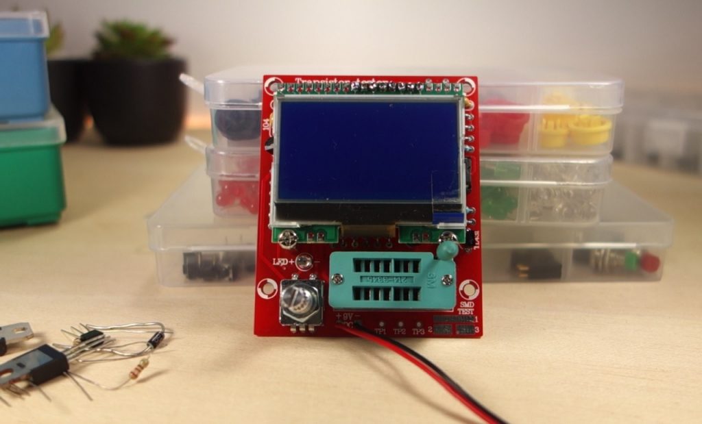
In this post we’re going to assemble and test a DIY transistor (component) tester kit. This particular kit is the Original Hiland DIY M12864 Transistor Tester Kit.
The component tester is a gadget that identifies different electronic components as well as their specifications. It identifies PNP and NPN bipolar transistor, N, P-channel MOSFET, JFET field effect transistors, diodes, resistors, capacitors, and inductors.
Where to Buy?
This product was sent to review from Banggood and you can click on the product card below to visit the product page.
Original Hiland DIY M12864 Graphics Version LCR ESR PWM Transistor Tester Kit
Watch the Video Review
You can watch the video review below of the DIY transistor tester kit or you can scroll down and continue reading.
Unboxing the Component Tester Kit
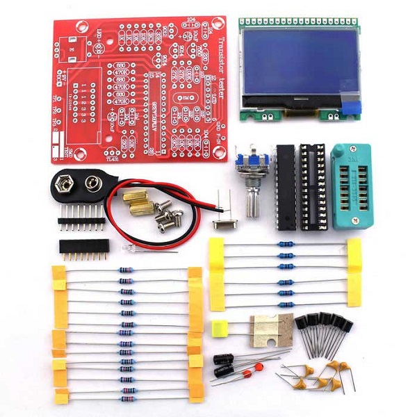
Inside the package you have all the components you need to build the component tester. These are all through hole components, so they are fairly easy to solder, even if you don’t have much experience.

Also, the PCB is well labeled. So you know exactly where to solder each component. The place to solder each resistor is also clearly labeled in the PCB.

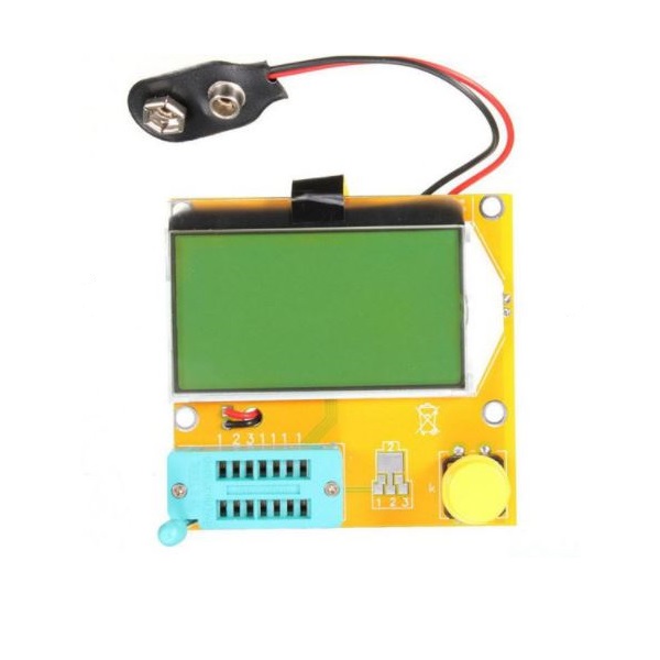
If you don’t want to solder, there’s also a version of this kit that comes pre-assembled. You can check this version below.
Assembling the Component Tester Kit
I started by identifying each resistor with my multimeter and label it. Resistors with the same value are grouped together. Then, insert all the resistors an their corresponding place and start soldering.
After soldering all the resistors, cut their leads at the back.
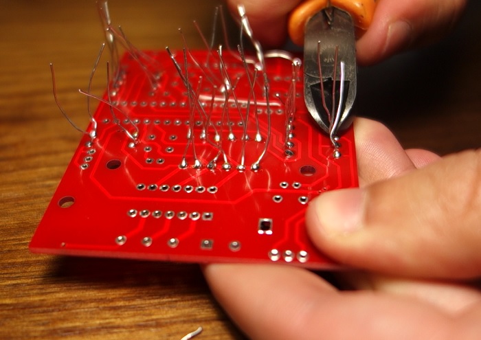
Then, you can add the other smaller components: like capacitors, the crystal, transistors, and the LED. Leave the taller components to solder at the end.
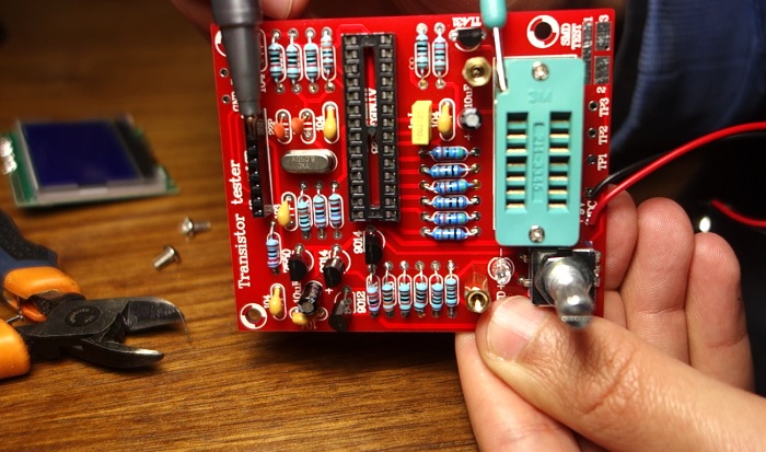
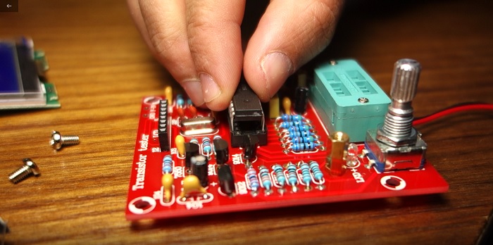
After soldering everything, insert the microcontroller as well as the LCD to the header pins.
Calibrating the Component Tester
Apply power to the component tester using a 9V battery. The first time you use it, you need to follow a calibration procedure.
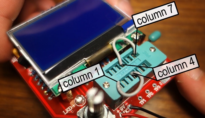
To start the calibration mode, you need short pins 1, 2 and 3 with two wires. You can do it as shown in the following figure. Then, press the button, and let the self test mode begin.
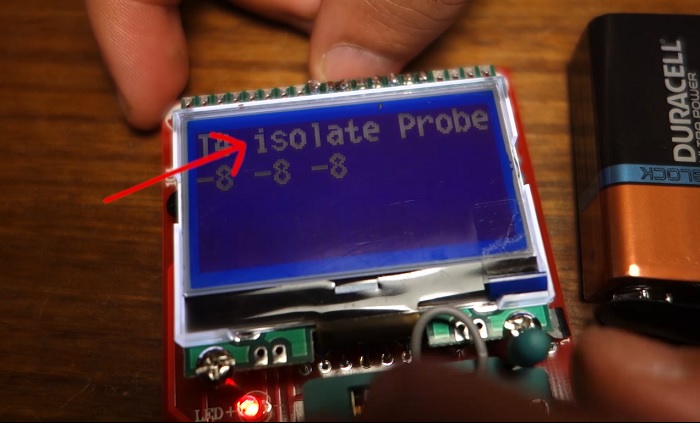
After a few seconds, you’ll see this message on the screen, saying to isolate probes. At this point, you should remove the wires.
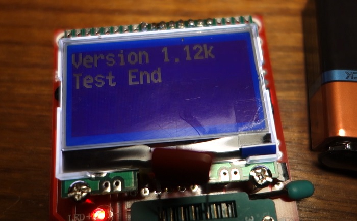
Finally, when it prompts this message, you need insert the extra capacitor that came in the kit into pins 1 and 3. Let it run for a few more seconds until the calibration is done.
Identifying Components with the Component Tester
Now, we can start testing components. The component tester is able to identify and measure different components like resistors, transistors, MOSFETs, capacitors, inductors and diodes.
The socket has 3 different pins. The first three columns are for pin 1, the fourth column is for pin 2 and the last three columns are for pin 3. To test your components make sure each lead is connected to a different pin.
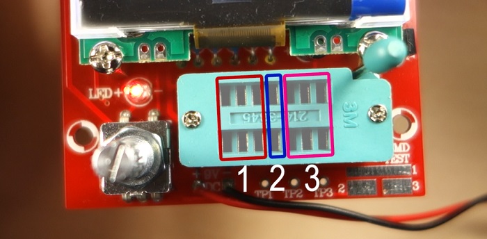
For example, if you’re testing a resistor, you can can connect one lead to pin 1 and the other lead to pin 2, or instead you can use pin 1 and 3, or pin 2 and 3. But the two leads can’t be connected to the same pin.
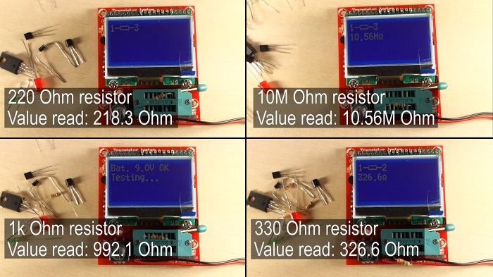
We tested different resistors and it works quite well. It even identifies a 10MOhm resistor.
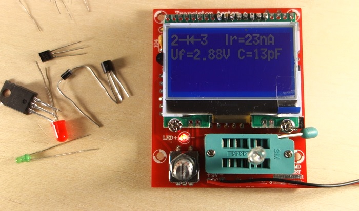
When testing diodes and LEDs, it shows which is the positive and negative lead as well as the forward voltage.
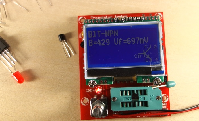
The transistors had not problem identifying.
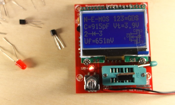
It also identifies MOSFETs.
Finally, you can test both ceramic and electrolytic capacitors. But make sure they are discharged, otherwise you may damage your component tester.
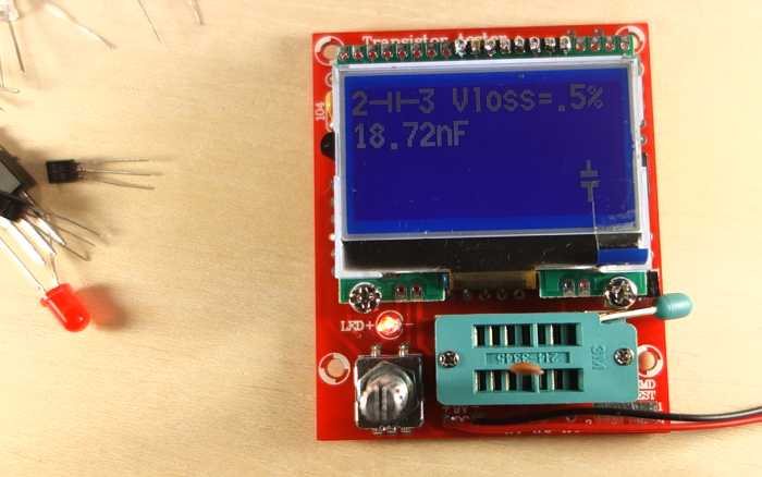
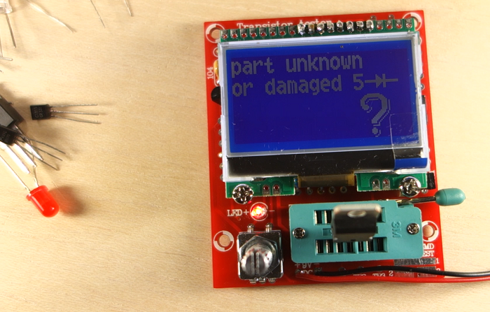
Keep in mind that if you try a voltage regulator it will not work. And some transistors might also not be properly identified.
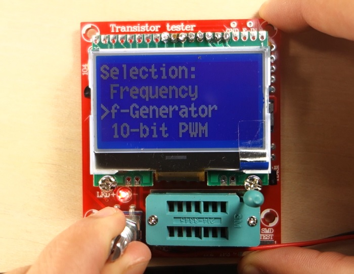
This kit has a few more functionalities that you can use, if you go to the menu you can change the contrast, generate square waves, generate PWM pulses with a signal generator. And It also has frequency meter function (to take advantage of this feature, you need to use the two pins at the top right corner labeled with GND and F-in).
You may also like:
- 4 DIY Kits You Can Build In a Weekend
- 8 Gadgets You Didn’t Know You Could Make With a DIY KIT
- 7 DIY LED Kits You’ll Be Proud of Building
Wrapping Up
After testing this kit, I think it identifies very well each component and it gives a very approximate value of the their main specification. Auxiliar values like Vloss, ESR sometimes are correct and other times are way off.
However, I think this component tester works quite well and for the price point is a good addition to your lab. Here’s the links if you want to get your component tester.
Looking for more great deals on electronics and tools? Make sure you subscribe here to catch upcoming deals and score some extra savings on your favorite gear!
[Recommended Course] Learn ESP32 with Arduino IDE
Register in our brand new ESP32 course with Arduino IDE. This is our complete guide to program the ESP32 with Arduino IDE, including projects, tips, and tricks! The registrations are open, so sign up now.
Other RNT Courses
 [eBook] Home Automation using ESP8266 »
Build IoT projects and home automation gadgets with the ESP8266 Wi-Fi module.
 [Course] Build a Home Automation System »
Build a home automation system using open-source hardware and software.
 [Course] Arduino Step-by-Step Projects »
Build 25 cool Arduino projects with our course even with no prior experience!
Leave a Reply