In this post we’re going to take a look and review the JYETech DSO150 digital oscilloscope. An oscilloscope is an essential tool in electronics but its price may be demotivating for electronics hobbyists. A cheap regular bench oscilloscope costs at least $300.
But, fortunately there are very cheap oscilloscope kits that can perform the most basic functions for a very low price. For example, the DSO150 low cost oscilloscope may cost between $20 and $40. This oscilloscope doesn’t replace a real oscilloscope, but it is good enough for hobbyists looking to debug low frequency signals or for learning purposes.
Where to buy?
This product was kindly sent from Banggood and you can click on the product card below to visit the product page. We’ve gotten the DSO150 assembled version with case that costs around $40. But now, you can get it with approximately 50% discount.
Original JYE Tech Assembled DSO-SHELL DSO150 Oscilloscope
$20.99
If you want to save some money, and you like soldering kits, you can get the kit version for approximately $25.
However, you should keep in mind, that these kits are a bit tricky to assemble and if you don’t have much experience soldering, you may not be able to get it working. So, if you don’t want to take risks, the assembled version will work straight away.
Related: Best Oscilloscopes for Beginners and Hobbyists
Watch the Video Review
You can watch the video review about the DSO150 digital oscilloscope, or you can scroll down and continue reading.
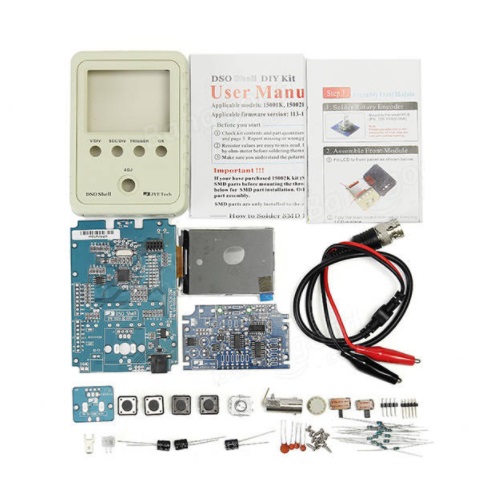
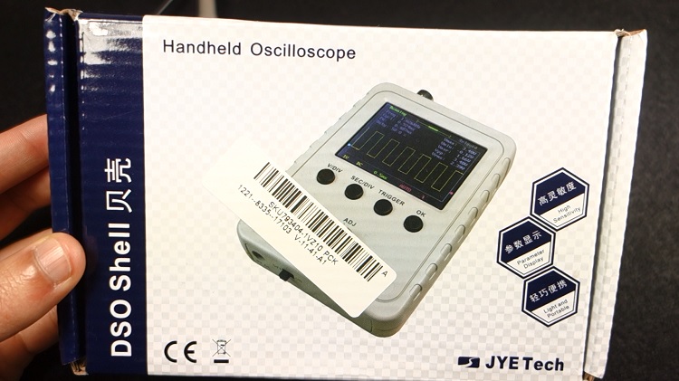
JYETech DSO150 Digital Oscilloscope Unboxing
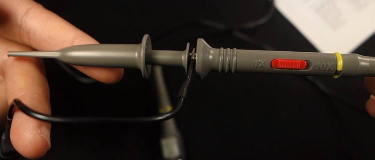
Alongside your oscilloscope you’ll get a probe that has 10x attenuation switch.
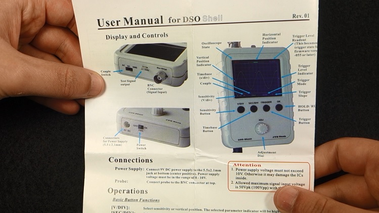
The product also comes with a one page instructions manual that has table describing some functions.
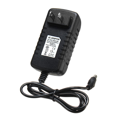
The oscilloscope needs a 9V DC power supply that doesn’t come included in the kit.
So, if you don’t have one, make sure you get a 9V power supply when you get your oscilloscope.
Note: if the power supply is sold out on Banggood, try to find the 9V power supply on ebay here.
DSO150 Oscilloscope Specifications
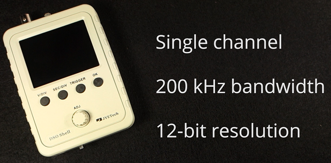
This is a very simple scope with a single channel, 200kHz bandwidth, and 12-bit resolution. This tool doesn’t replace a real oscilloscope, but it is good enough for hobbyists looking to debug low frequency signals or for learning purposes.
Here’s the DSO150 Oscilloscope specifications:
- Number of channels: 1
- Analog bandwidth: 0 – 200KHz
- Sensitivity: 5mV/Div – 20V/Div
- Resolution: 12-bit
- Input Impedance: 1M ohm
- Coupling: DC, AC, GND
- Timebase: 10us/Div – 500s/Div
- Trigger modes: Auto, Normal, Single
- Trigger types: Rising/falling edge
- Power supply: 9V DC
- Supply current: 120mA @ 9V
- Dimension: 115mm x 75mm x 22mm
- Weight: 100g
DSO150 Oscilloscope Features
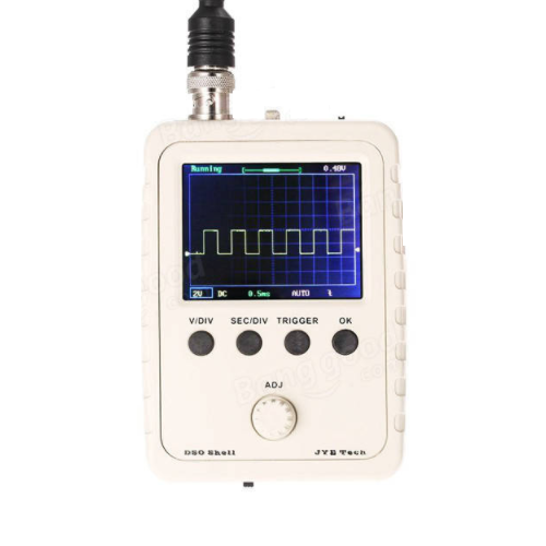
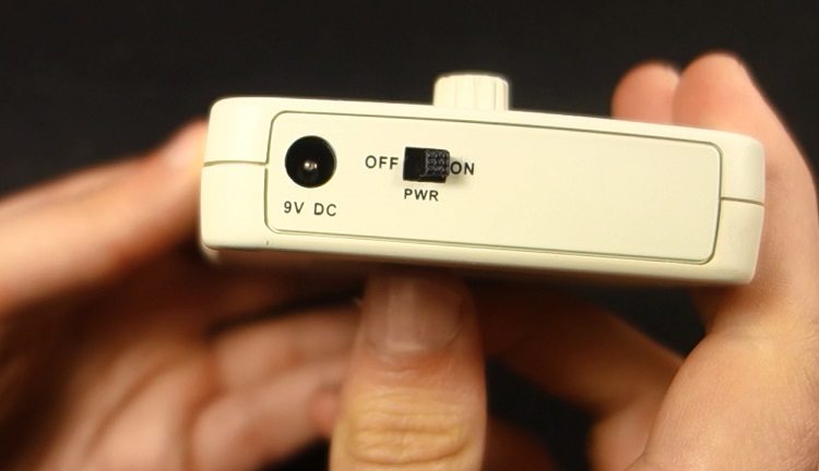
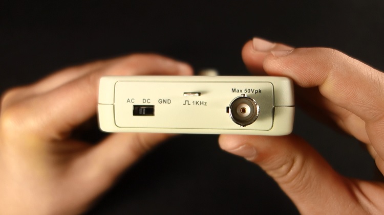
The DSO150 oscilloscope is fairly straightforward to use. It comes with an on and off switch at the bottom. At the top, there’s a switch to choose between GND, DC, or AC coupling.
The BNC connector is also at the top, which is where you should connect your probe. The oscilloscope comes with 1kHz square wave generator that you can use for testing purposes.
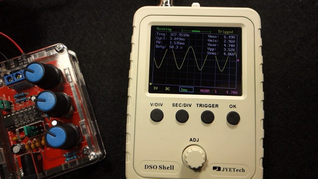
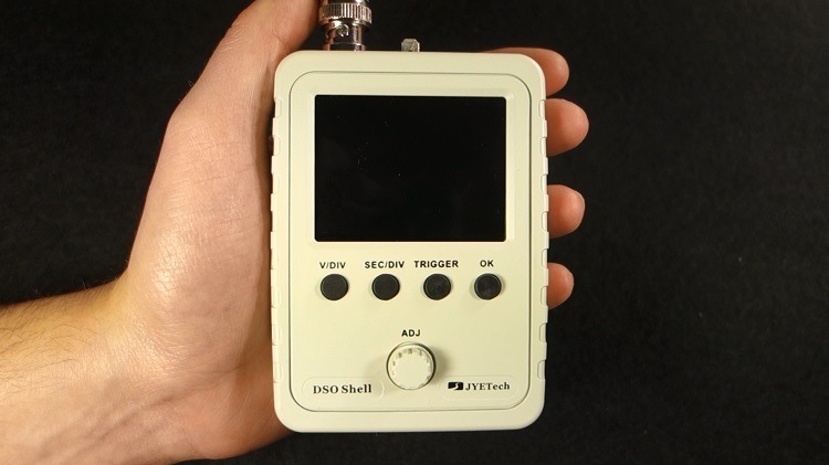
At the front, you have four buttons: voltage division, time division, trigger, and ok. And there’s also a rotary encoder to adjust the parameters.
Testing the DSO150 Oscilloscope
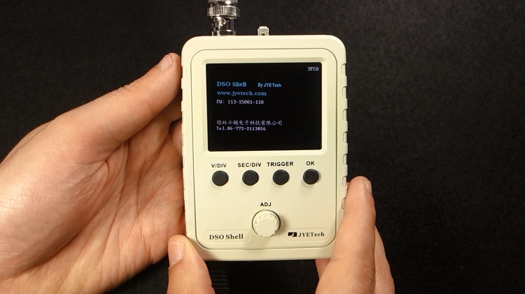
So, let’s test this oscilloscope. Apply power using a 9V DC power source, turn it on using the ON/OFF switch, and wait a moment while it boots.
After that, connect the probe to the 1kHz square wave generator.
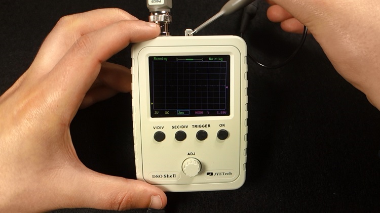
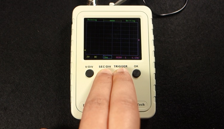
Hold the SEC/DIV and TRIGGER buttons simultaneously to reset to the default settings.
Voltage division
Now, if you click the Voltage Division button, the voltage division value gets highlighted with a blue color, and you can adjust the voltage scale. You can select a voltage division from 5mV to 20V.
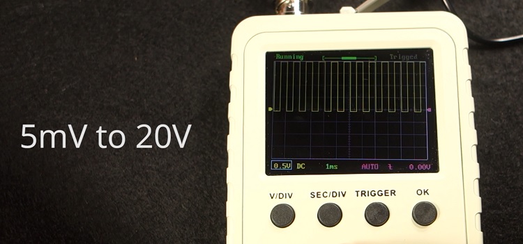
If you press the button again, the left little arrow turns blue, which means you can rotate the knob to adjust the vertical alignment.
Hold down the TRIGGER button, so that the screen shows a steady image.
Time division
With the SEC/DIV button, you can adjust the time scale. You can select a time division as small as 10μs or as big as 500s. However, if you select a big time division it will probably get stuck.
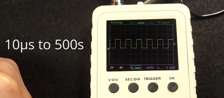
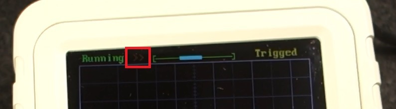
If you press the button again, the bar at the top turns blue and you can navigate through the time sampled. You can press the Rotary Encoder, and two little arrows will appear at the top. That means you are in fast mode adjustment.
Press the Rotary Encoder again, to go back to the slow mode adjustment. You can freeze the signal by pressing the OK button and better analyse the wave. Press again to unfreeze.
Trigger options
There are three trigger options: auto, normal, and single, and you can select rising edge or falling edge. You can also adjust the trigger level. When the arrow at the right turns blue, you just need to rotate the knob to adjust the trigger level. If you hold the TRIGGER button, it will set the trigger level to the signal’s amplitude middle value.
Freeze the signal
As we’ve seen previously, you can press the OK button to freeze and unfreeze the signal. Please note that when you freeze the wave you cannot adjust the scales.
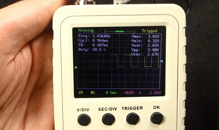
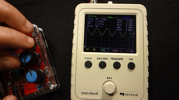
Taking measurements
If you hold the OK button, you can get some measurements: like the frequency, duty cycle, maximum voltage, etc… So, this scope can also act as a measurement tool. It’s not very accurate, but it gives you an idea of the values.
Testing with Arduino PWM Signals
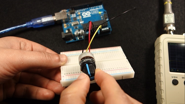
Now, let’s test a different setup. In this example we have an Arduino that is generating a PWM signal. The duty cycle of the PWM signal can be adjusted by rotating the potentiometer.
If you want to test this setup, you need the following parts:
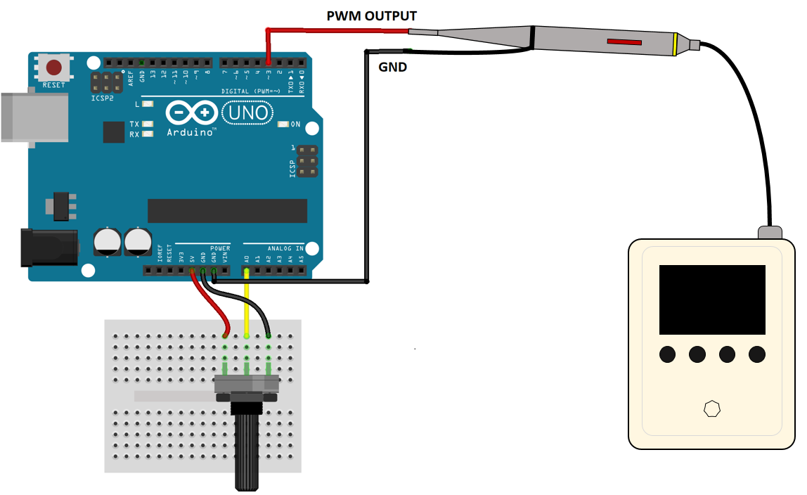
Follow the next schematic diagram:
Upload this code to your Arduino board:
Related content: Learn more about the Arduino, sign up for our free Arduino Mini Course
Demonstration
Connect the probe to the output pin that is generating the PWM signal, and GND to the Arduino GND pin. Let’s test it.
The signal increases or decreases the duty cycle as we rotate the potentiometer.
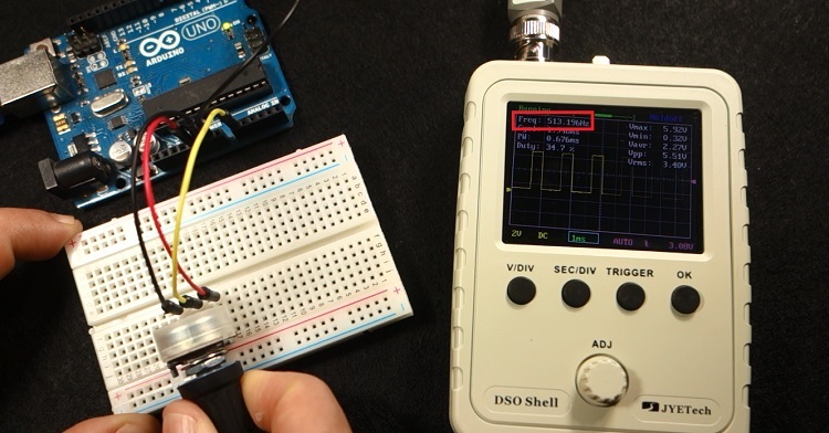
As you can see we are receiving square signals with approximately 500 Hz frequency. Which is the frequency of these Arduino PWM signals. The signal looks great on this oscilloscope, and clearly gives you an idea on what’s going on.
To learn more about signals, you can also use a low-cost function generator like the XR2206 function generator DIY kit to test different wave types with adjustable frequency and amplitude.
We also have a review about the XR2206 function generator, feel free to take a look.
Wrapping Up
In summary, this is a great oscilloscope given its price. Although it cannot be compared with a real oscilloscope, if you just want to measure duty cycle of PWM signals, read low-frequency periodic signals, or debugging signals from your Arduino circuits, it works just fine. So, if you’re an electronics hobbyist looking for a very cheap oscilloscope to debug and learn more about your circuits, this could be a great option.
If you’re looking for a “real” oscilloscope for a very reasonable price, we recommend taking a look at the Hantek DSO5102P Digital Storage Oscilloscope (DSO) (or read Oscilloscopes buying guide).
We also have other articles about oscilloscopes and DIY kits that you may like reading:
- Best Oscilloscopes for Beginners and Hobbyists
- DIY Transistor Tester Kit Review
- XR2206 Function Generator DIY Kit Review
- 8x8x8 LED Cube DIY Kit – How To Build and Review
We hope you’ve found this review about the DSO150 low-cost oscilloscope useful. Thanks for reading.
[Recommended Course] Learn ESP32 with Arduino IDE
Register in our brand new ESP32 course with Arduino IDE. This is our complete guide to program the ESP32 with Arduino IDE, including projects, tips, and tricks! The registrations are open, so sign up now.
Other RNT Courses
 [eBook] Home Automation using ESP8266 »
Build IoT projects and home automation gadgets with the ESP8266 Wi-Fi module.
 [Course] Build a Home Automation System »
Build a home automation system using open-source hardware and software.
 [Course] Arduino Step-by-Step Projects »
Build 25 cool Arduino projects with our course even with no prior experience!
I purchased one of those kits 2 years ago. It came in the mail to the RV Park where we were wintering, and I got all excited, sort of like a kid with a new toy! Put it all together, and guess what? Only about half the functions worked, and then they were only partially working. I tinkered with the blasted thing for the next year and a half. Lost the bottom plate that protects the switch. Then one day, I was posting on a help forum and suddenly I read what I had posted, and it became CLEAR to me. The rottery encoder was not working properly. So I ordered 10 new encoders, and put one of them in the circuit, and suddenly it all started working once more. So I was again a happy camper, on and since I could not get it working, I did buy a different model and it works OK, and before that, I built a small simple one using an arduino, it works, and I built one that is a soundcard model for my laptop, that works as well, so I can really look at stuff now with all my toys.
Hi Jerry.
Thanks for sharing your opinion.
We had no problem at all with our Oscilloscope. It worked well straight away. But we got the assembled version.
Sometimes when you get these tools as a kit, it may be a bit tricky to assemble them and get them working properly. Or you may happen to get a faulty one.
Regards
Sara 🙂
Shell for battery pack on ebay
Thanks for sharing!
Bought one of these little scopes as a kit, and assembled it together. Works fine.
However, note that you need a clean DC source to power the scope. A 9V battery works fine, but will not last very long. A cheap switching type 9V power supply (such as recommended on this page) is unfortunately not suitable, as the switching noise effectively corrupts the scope’s input signal and makes it it unuseable in the millivolt range. A good quality linear DC supply (transformer, diode bridge, capacitors and linear regulator) would be a good solution, although even that is not portable.
You’re definitely correct using a clean DC source is a must for accurate readings. Thanks for your helpful feedback!
Thanks for leaving this comment! I attached a 9v battery holder and was enjoying noise-free operation for quite a while. After some time (several short uses over a period of 6 weeks) I noticed a prominent saw-tooth background noise and couldn’t guess what could be causing it. After reading this comment, I checked the battery and it read only 7.5v. After replacing all is well. Note to any others using batteries: disconnect the plug when not in use. I feel the unit pulls a small a small current when switched off, contributing to the shorter battery life.
Thank you for this clear review. Because of this I now know exactly what I wanted to know. So I’m going to purchase the oscilloscope and use it next to my regular scoop for testing and repairing audio equipment.
That’s great!
The link to the “9V” supply shows a 12V supply.
This link seems to do the job for only $3.33 : banggood.com/9V-1A-Power-Supply-Adapter-US-Plug-2-Flat-Pin-For-Arduino-p-916174.html?rmmds=search&cur_warehouse=CN
US$1.58 via Priority Direct Mail. Shipping time:7-15 business days.
Hi John.
Thank you for noticing.
It was my mistake. It is fixed now.
Regards,
Sara 🙂
Thanks for the driving overview! I built this yesterday, followed the calibration on the sheets provided and then thought, “Cool, now what?”. LOL.
You have given me some great pointers, especially holding down the OK button to get extra information.
I would like to now integrate a LiPo battery inside the unit to make it more portable. I saw above a person mention an ebay link, but the link is not there.
Another great tutorial, I purchased the self-build version which is relatively easy to build and it works fine. I have always wanted my own scope and this is perfect for me as I am just learning the basics of the Arduino and others. Thank you Sara And Rui.
That’s great!