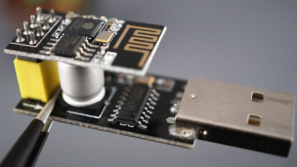
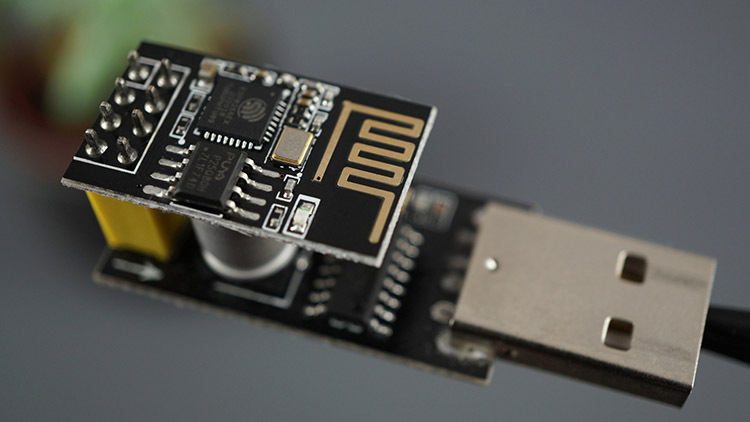
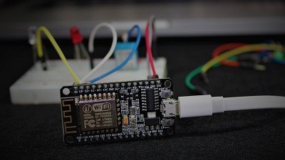
This module is a USB programmer for ESP8266 modules of type ESP-01. This is a convenient programmer module because you need to connect the ESP-01 to the module and the module to your computer to program the ESP8266.
However, we don’t think this is a good programmer because you must modify it to make it work properly. However, I know that many of our readers have this programmer and experience problems flashing new sketches when they first try it. So, we wrote this guide that explains how to fix the ESP-01 USB Serial Programmer “issue”.
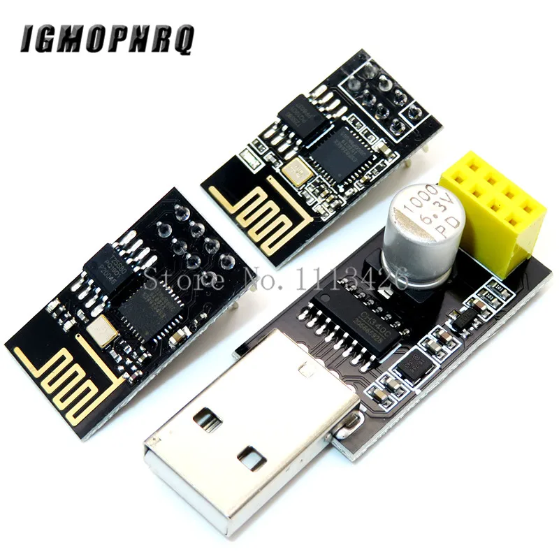
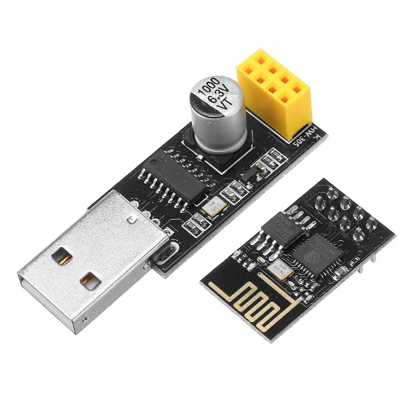
Where to Buy ESP-01 USB Programmer
You can grab an ESP-01 USB Serial Programmer at one of these stores (even newer programmers might still have the programming “issue”).


Installing CH340 Drivers
This module is based on the USB-UART bridge CH340 chip, so you must have the CH340 drivers installed on your computer to upload code to the ESP8266-01.
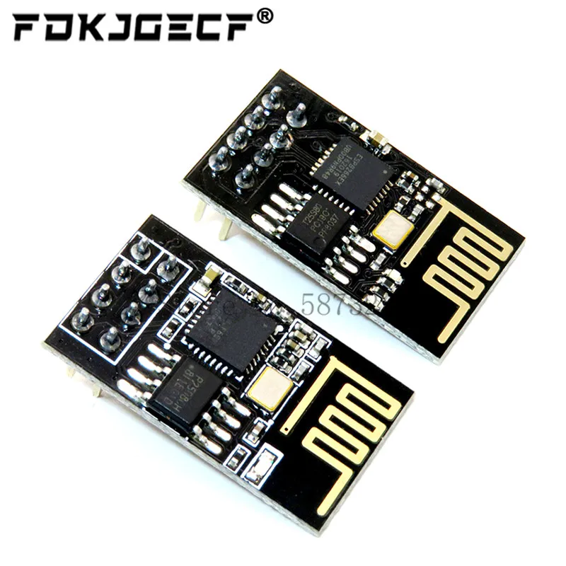
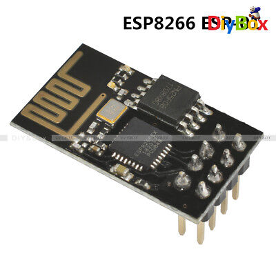
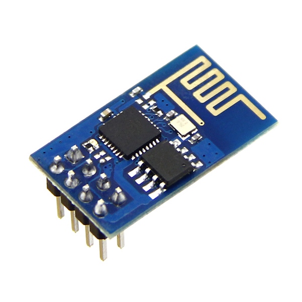
ESP-01 Board
If you don’t have an ESP-01, you can get one in the links below.


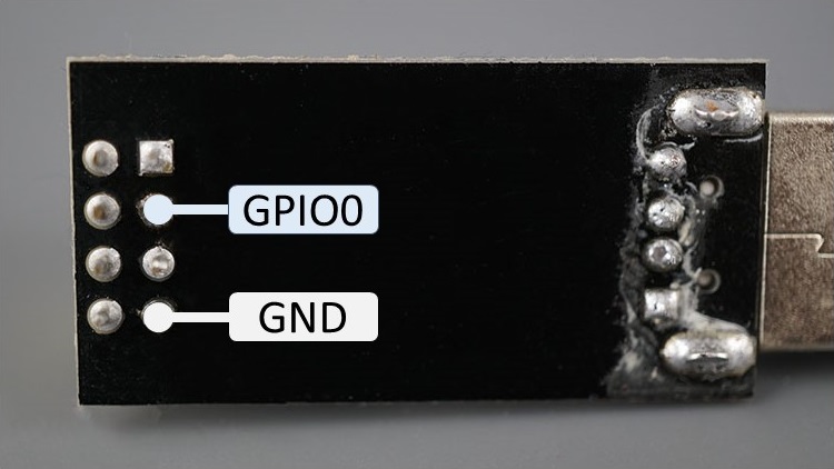
ESP-01 USB Serial Programmer Pins
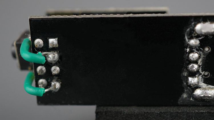
To make the ESP-01 go into Serial Programming mode, GPIO 0 needs to be pulled to GND – which doesn’t happen in the original module. As you can see in the figure below, GPIO 0 is not connected to GND.
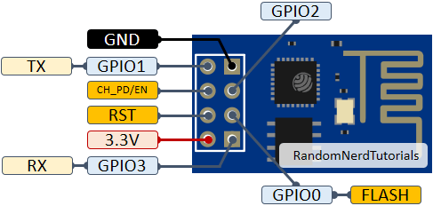
For a reference, here’s the ESP-01 pinout.
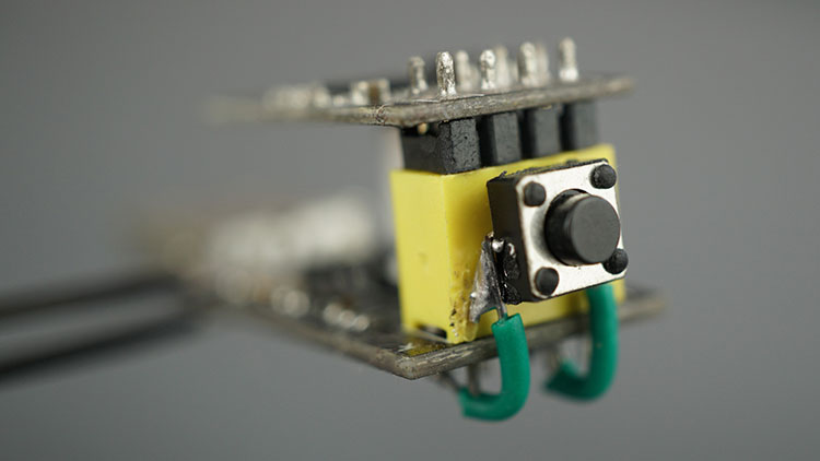
To pull GPIO 0 to GND to make the ESP-01 go into programming mode, you can solder a pushbutton to the ESP-01 USB Serial Programmer between GPIO 0 and GND pins, as shown in the following figures.
Here’s the final result:
Programming the ESP8266 ESP-01 with the USB Serial Programmer
Now that you have your Serial Programmer fixed, we’ll show you how to program the ESP-01 using this module. Attach the ESP-01 board to the USB Serial programmer as follows.
Then, follow these steps:
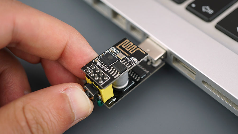
- Hold down the soldered pushbutton;
- While holding down the pushbutton, plug the ESP-01 USB programmer into your computer.
Note: if you don’t hold-down properly the pushbutton before plugging it into your computer, your ESP-01 might fail to boot in flashing mode, causing an error uploading new code.
Open your Arduino IDE and having the ESP8266 Board installed. Select the board “Generic ESP8266 Module” and the right COM Port.
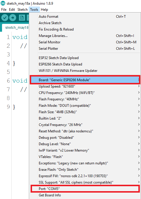
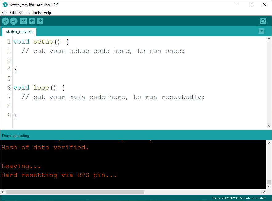
After that, press the “Upload” button to flash an empty sketch to your board. After a few seconds, you should see the “Done Uploading” message.
[SOLVED] esptool.FatalError: Failed to connect to ESP8266
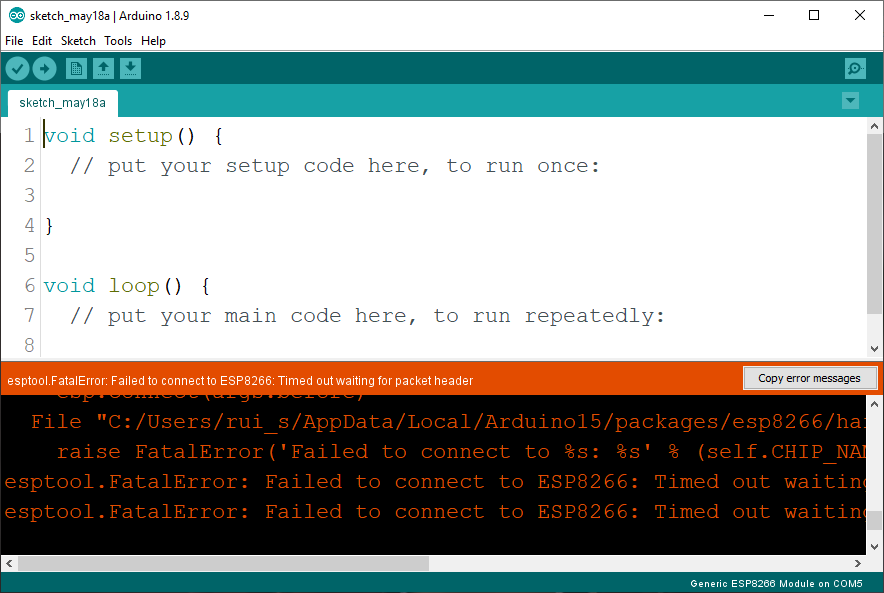
If you see the following error message when you try to upload a new sketch to your ESP-01:
esptool.FatalError: Failed to connect to ESP8266
Timed out waiting for packet header
This means that your ESP-01 didn’t go into flashing/uploading mode, so it can’t receive a new code.
One of the ways to solve this problem is to remove the board from your computer and restart the process.
- Remove the ESP-01 USB programmer from your computer;
- Hold down the soldered pushbutton;
- While holding down the pushbutton, plug the ESP-01 USB programmer into your computer;
- Ensure that the programmer Port is selected in your Arduino IDE;
- Press the Arduino IDE “Upload” button.
You might also try to hold down the soldered pushbutton while uploading a new sketch. If you continue to see that error, check with a multimeter that your pushbutton is soldered properly and it’s connected to the right GPIOs.
Wrapping Up
We hope that you’ve gotten your ESP8266 ESP-01 USB Serial Programmer with CH340 Chip to work properly with this article. After fixing the issue, you’ll see that this module is convenient to upload code to an ESP-01.
If you intend to get a USB Serial Programmer like this one, consider that you need to make a few modifications to make it work.
- Read our ESP8266 Troubleshooting Guide for more tips
- To learn more about the ESP8266, grab our eBook “Home Automation Using ESP8266“
- Read our free 110+ ESP8266 NodeMCU Projects
Thanks for reading.
[Recommended Course] Learn ESP32 with Arduino IDE
Register in our brand new ESP32 course with Arduino IDE. This is our complete guide to program the ESP32 with Arduino IDE, including projects, tips, and tricks! The registrations are open, so sign up now.
 [eBook] Home Automation using ESP8266 »
 [Course] Build a Home Automation System »
 [Course] Arduino Step-by-Step Projects »
This was a great Idea. I added this switch (GPIO 0 to GND but I also added another one from the Reset pin to Ground.
Now, I can leave the circuit plugged in the USB port and when I want to put the 8266 into programming mode I just press FIRST the reset button – keep it presses and then press the GPIO 0 to ground button while releasing the reset button.
The module goes into programming mode without having to unplug the usb port. I find it easier than unplugging and plugging the usb port while trying to hold the button down…!
Thanks for the original tip.
The original tip and your addition together are perfect.
Thanks!
Thanks, been needing this!
Hi Rui and Sara,
Thanks for all your work in making things accessible 🙂
One comment on the addition of a programming button, I got this one (https://smile.amazon.co.uk/gp/product/B07G6ZPY9D) which has a slide switch, rather than a momentary switch, and I find it works flawlessly.
I didn’t realise the benefit of the switch at the time – I chose this one, as it doesn’t have the large capacitor (?) which looks like it would hit the underside of the ESP-01 board.
Keep up the good work – I am making my way through your ESP-CAM book now, and have the rest if the IOT bundle to do after!
Thanks a lot,Exactly what i was looking for.saved my day!
Thank you for this idea with a pushbutton! I did the same, and it works nicely.
Just came here to thank you, great guide!
I prepared programmer use CH340E with ATTINY13 to manage programing signal for arduino. Programer use DTR and TX signal to Attiny13 to set GPiO2 signal after reset signal. ATthe end when signal TX not sending signal after 1 second attiny send signal “RESET”
I not use any switch button.