Do you want to get started with ESP8266? Then, read this post to figure out the best ESP8266 Wi-Fi Development Board for your project requirements.
The ESP8266 is a $4 (up to $10) Wi-Fi module. It allows you to control inputs and outputs as you would do with an Arduino, but it comes with Wi-Fi.
There’s a new board called ESP32, so you might like reading Best ESP32 Development Boards.
Comparing the ESP with other Wi-Fi solutions on the market, it is a great option for most “Internet of Things” projects! It’s easy to see why it’s so popular: it only costs a few dollars and can be integrated into advanced projects. Additionally, it is compatible with Arduino IDE. So, if you’ve worked with Arduino before, you’ll easily get used to working with the ESP8266.
We’ve published dozens of free ESP8266 projects and tutorials. One of the best projects to experiment with your ESP8266 when you’re getting started is building a simple web server to control outputs.
Recommended resource: Home Automation using ESP8266 eBook
Best ESP8266 Boards Comparison
At the moment, there are a wide variety of development boards with the ESP8266 chip that differ in the number of GPIOs, antenna styles, size, breadboard compatibility, etc…
We’ve created an in-depth ESP8266 Pinout reference guide covering exactly what each pin does and how to use them.
The best ESP8266 development board for your project will depend on what you intend to do. We’ll just cover a short selection of the most popular ESP8266 boards. The table below shows a quick comparison of the boards. Continue reading this post for a more in-depth analysis.
ESP-01 | ESP-12E NodeMCU | Wemos D1 Mini |
|
|---|---|---|---|
 |  |  |
|
Links | |||
GPIOs | |||
ADC Pins | 1 | 1 | 1 |
Flash Memory | 1MB (upgraded version) | 4MB | 4MB |
Breadboard-friendly | X | ✓ | ✓ |
USB to Serial Converter | X | ✓ | ✓ |
Size | 24.75mm x 14.5mm (0.97'' x 0.57'') | 48.55mm x 25.6mm (1.91'' x 1'') | 34.2mm x 25.6mm (1.35'' x 1'') |
Price | $ | $$ | $$ |
Recommended reading: ESP8266 Pinout Reference: Which GPIO pins should you use?
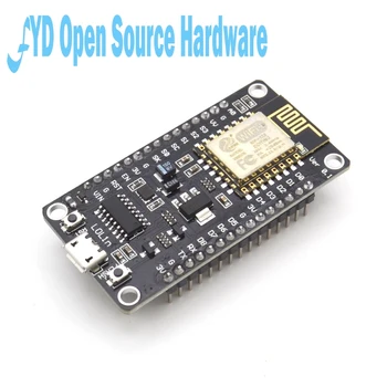
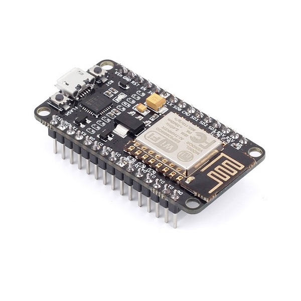
ESP8266 12-E NodeMCU Kit
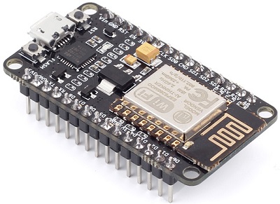
The ESP12-E NodeMCU Kit is one of the most used ESP8266 development boards. It features 4MB of flash memory, access to 11 GPIO pins, and one analog-to-digital converter (ADC) pin with 10-bit resolution. In addition, the board has a built-in voltage regulator, and you can power up the module using the mini USB socket or the Vin pin.
Uploading code to the board is as easy as uploading code to the Arduino. There’s no need for an FTDI programmer, as it comes with a USB-to-serial converter built-in.
This is the ESP8266 board model we use more often in our Wi-Fi and IoT projects. It is very versatile, and it’s great for beginners. So, if this is your first time with the ESP8266, this module is a great choice. Take a look at the links below to find out the ESP8266 12-E NodeMCU kit on your favorite store.


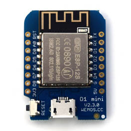
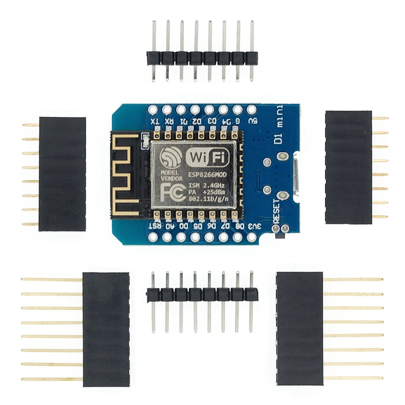
WeMos D1 Mini
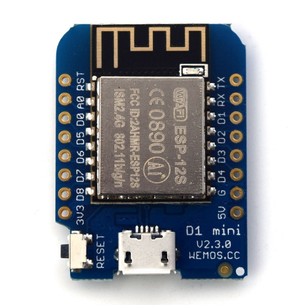
The WeMos D1 Mini offers 4MB flash memory, 11GPIOs, 1 ADC pin in a minimal and small setup. So, if you need something that consumes less power for a more economical project, this is a good option. Additionally, the community has developed a wide variety of shields for the D1 mini board, which allows you to build small and simple setups with almost no wiring required. The WeMos D1 mini board is also a great option for beginners.
However, the board doesn’t come with the header pins soldered, so you need to solder them yourself. If you need a soldering iron, you can check the recommend soldering irons for beginners.
The WeMos D1 mini board costs around $4 depending on the store. Check the links below to find the board on your favorite store.


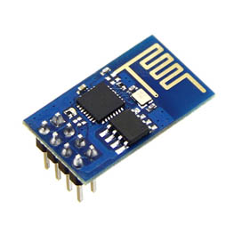
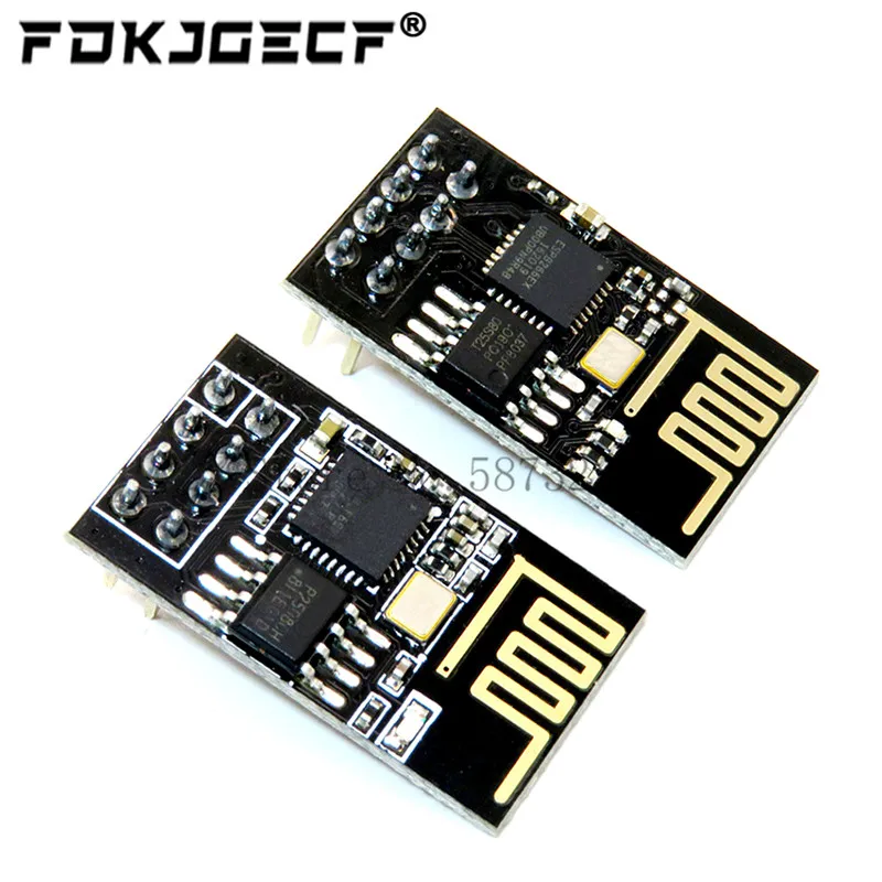
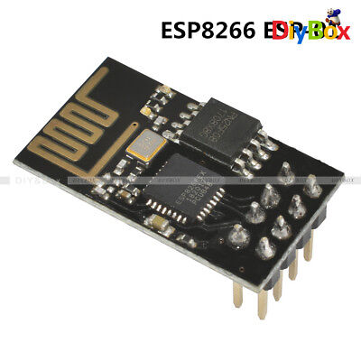
ESP8266 ESP-01

The ESP-01 is very small and fits in any enclosure, so it is perfect for finished projects. The upgraded version features 1MB flash memory (the previous version had 512 kB). In addition, it offers four GPIOs to control and connect peripherals (two of which are TX and RX for serial communication). So, if you need more peripherals in your projects, it is better to use one of the previous boards.
Unfortunately, the board doesn’t have a built-in voltage regulator, so you need to use a 3V3 power source or add a voltage regulator to drop the input voltage to 3V3. Additionally, it doesn’t come with a USB to serial converter, which means you need an FTDI programmer to upload code to the board. If you want to get started with the ESP-01, read our getting started guide.
The ESP-01 is great for applications that require a small number of peripherals. However, if this is your first time using the ESP8266, we recommend getting one of the previous boards. Those are more beginner-friendly and more versatile.
This is the cheapest ESP8266 module. Check the links below to find the ESP-01 on your favorite store.


Recommended resource: Home Automation using ESP8266 eBook
Need Help Getting Started with the ESP8266?
The ESP8266 made Wi-Fi and IoT projects more accessible to makers, hobbyists, and general public due to it’s great features, easiness to use, and affordable price. If you want to build your own IoT project, and need some help getting started, we have several resources for you.
Home Automation with the ESP8266
This is our premium ESP8266 course. Learn how to use your ESP8266 to automate your house. Even if you are an absolute beginner, you’ll be able to follow along and came up with your own IoT projects. You can get access to the course here.
ESP8266 Projects
We have dozens of free projects with the ESP8266. Here’s a short list of some of our most popular projects:
- ESP8266 Web Server
- ESP8266 DHT11/DHT22 Temperature and Humidity Web Server with Arduino IDE
- Voice Controlled Relay – Alexa with ESP8266
- ESP8266 Wi-Fi Button – DIY Amazon Dash Button Clone
- ESP8266 Remote Controlled Sockets
You can also search all our ESP8266 projects.
Wrapping Up
In this article, we’ve taken a look at three different ESP8266 development boards: ESP8266 12-E NodeMCU Kit, WeMos D1 Mini, and ESP-01. Of course, there are many more different boards available, but we reviewed the ones we use more often, which are also the most popular.
We recommend the NodeMCU Kit or the WeMos D1 Mini because both boards have a built-in programmer chip, making it easy to upload code. Additionally, they also offer a reasonable number of GPIO pins. If you are a beginner, you should go for one of these boards. However, if you need a tiny board for your project and only need 2 GPIOs, the ESP-01 is a better and cheaper alternative.
In this post, we’ve shown you and compared our favorite Best ESP8266 Wi-Fi Development Boards. These are perfect to use in your Internet of Things (IoT) projects. So which one is your favorite?
You might also like reading:
- ESP32 vs ESP8266 – Pros and Cons
- ESP32 Development Boards Review and Comparison
- ESP8266 Pinout Reference
Looking for more great deals on electronics and tools? Make sure you subscribe to catch upcoming deals and score some extra savings on your favorite gear!
[Recommended Course] Learn ESP32 with Arduino IDE
Register in our brand new ESP32 course with Arduino IDE. This is our complete guide to program the ESP32 with Arduino IDE, including projects, tips, and tricks! The registrations are open, so sign up now.
 [eBook] Home Automation using ESP8266 »
 [Course] Build a Home Automation System »
 [Course] Arduino Step-by-Step Projects »
Yesterday I bought two books:
– Home Automation Using ESP8266 – 3rd Edition – Rui Santos.pdf and
– Troubleshooting Guide for the ESP8266.pdf
I use the ESP 8266 01
No solution could be found in the documentation above to solve this fault:
Archiving built core (caching) in: error: espcomm_upload_mem failed
Could you give me any advise?
Best Regards Hans
Hi Hans.
That error means that your FTDI programmer isn’t establishing a serial communication with your ESP8266.
We recommend following the next steps:
1. You need to double check the TX and RX connections.
2. You might also need to reboot your ESP while GPIO 0 is connected to GND (before trying to upload), to ensure that your ESP boots in uploading mode.
3. Or it might be a power issue (your ESP might need more current than your USB can provide).
I hope this helps.
We also recommend using this blog post: https://randomnerdtutorials.com/esp8266-troubleshooting-guide/ to write your questions or technical problems regarding the ESP8266 in the comments section.
Thanks 🙂
Two issues with this article. You said the ESP-12E NodeMCU and Wemos D1 Mini both have 11 GPIOs but then said the ESP-01 only has 2. ALL of these boards have the TX0 and RX0 pins broken out so the ESP-01 has FOUR GPIOs, not just two (or, if you say those can’t be used while debugging via the serial port, then the ESP-12E NodeMCU and Wemos D1 Mini should be listed as only 9 GPIOs each as two of their GPIO pins are the TX0 and RX0.)
Also on the NodeMCU, you stated that “The board has a built-in level shifter and you can power up the module using the mini USB socket or the Vin pin.” A “level shifter” is understood by most people as a “LOGIC level shifter” and not a part of the circuitry that simply lowers (or raises) the power supply voltage. Yes, you can POWER then from 5v (or even higher, via the Vin pin) but that doesn’t mean they will accept 5V in or put out 5V on any of the GPIOs.
Hi Mike.
You are right! Thanks for noticing that, and we’ve updated the article with your suggestions.
For some reason, we were using the term level shifter instead of voltage regulator.
Thanks 🙂
the ESP8266 Witty Cloud, about $3.50 on ebay and aliexpress, is also really good for development. it’s similar to the WeMos and comes in two boards. the bottom one has the voltage regulator and the USB programmer, so you can program it, pop it out, and use it in a circuit without the power overhead of the other piece.
Hi Mahesh.
I wasn’t aware of that ESP8266 board. It seems very practical.
Thank you so much for sharing!
Regards,
Sara 🙂
also, as a nice freebie, the USB part is CH340 based, so i’ve used it to program scores of devices such as arduino pro minis, attinys and other ESP8266s that don’t have integrated USB-serial. forget FTDI :-).
Another difference in these boards is whether boot mode is automatic.
The Wemos boards have automatic programming using some extra transistors and rs232 control signals.
The Nodemcu boards require holding the boot button while pressing and releasing the reset button to enter boot mode, then after programming you must push reset to get back out of boot mode.
You might want to mention OTA (over the air) programming. By including a small bit of extra code in your program, you can upload new versions of your code over Wi-Fi. The first thing I do with a new esp board is install an upload only sketch via serial and from then on all uploads are via Wi-Fi – which is significantly faster than serial upload. I can still use the serial port for debug messages while using Wi-Fi for uploads.