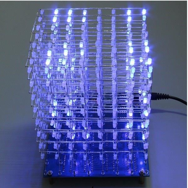
The 8x8x8 LED Cube DIY kit from Banggood is just awesome! But assembling and soldering all those LEDs without the right instructions can be a nightmare, and in the end, your LED cube may not work. To prevent this from happening, in this post we’re going to review and assemble the 8x8x8 LED Cube DIY kit, and we’ll show you all the steps you need to follow to build your LED cube successfully.
Note: it seems that some LED cubes don’t come programmed with the lighting effects. If that’s the case, you’ll have to program the cube yourself. We provide links for programming instructions at the end of this article.
Watch the Video Tutorial
The following video contains the steps you need to follow to assemble the cube. For written instructions with pictures, continue reading this post.
Before Getting Started
Here’s some important notes before getting started:
- We highly recommend reading the post until the end before start assembling your cube;
- This guide may also be useful for LED cubes from other stores. However, they might be slightly different, so we can’t assure the instructions will work, but they can be used as a reference;
- Your cube kit from Banggood might be slightly different. So, always troubleshoot in each step, and carefully analyse your kit before getting started;
- This kit requires a lot of soldering, so you need to know how to solder;
- We took approximately two days to make the cube (16 hours total). We made each step carefully and we recorded the process, so you may complete your cube in less time. However, it really depends on your skills, and if your’re building it in a rush or not;
- The kit doesn’t come with instructions. There are some instructions at the product page, but we didn’t find them very useful;
- Some recent LED Cube Kits don’t come programmed by default. So, you’ll need to program the LED cube yourself.
Where to Buy?
The Geekcreit 8x8x8 LED Cube DIY Kit was kindly sent to review from Bangood. You can click on the product card below to visit the product page.
Geekcreit® 8x8x8 LED Cube 3D Light Square Blue LED Electronic DIY Kit
$17.99
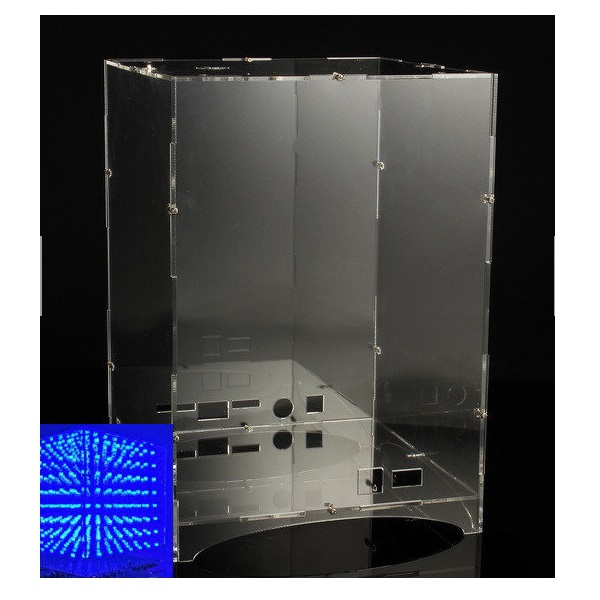
After assembling, your cube may be easily subjected to breakage, and that’s why we recommend getting an enclosure to place your cube. There is a specific enclosure for this cube.
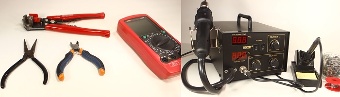
Necessary Tools
To assemble the cube, you’ll need the following tools and materials, besides your kit:
- Soldering iron – read Best Soldering Irons for Beginners and Hobbyists
- Soldering accessories like: solder, solder wick, cleaning sponge, circuit board holder, rosin flux, etc. Take a look at the top 10 soldering accessories and tools.
- Needle nose pliers
- Wire stripper – read Best Self Adjusting Wire Stripper
- Wire cutter
- Cardboard – to build a grid to mount the LED grids
- Multimeter – for troubleshooting purposes – read Best Multimeters Under $50
- USB-to-TTL Serial converter to program your cube if it doesn’t come programmed by default
- (Someone to help you out in some of the assembling steps)
Kit Parts
Your kit should come with the following components:
- 550 LEDs – our kit came with 3mm blue LEDs
- PCB
- Plastic storage box with electronic components
- Power cable
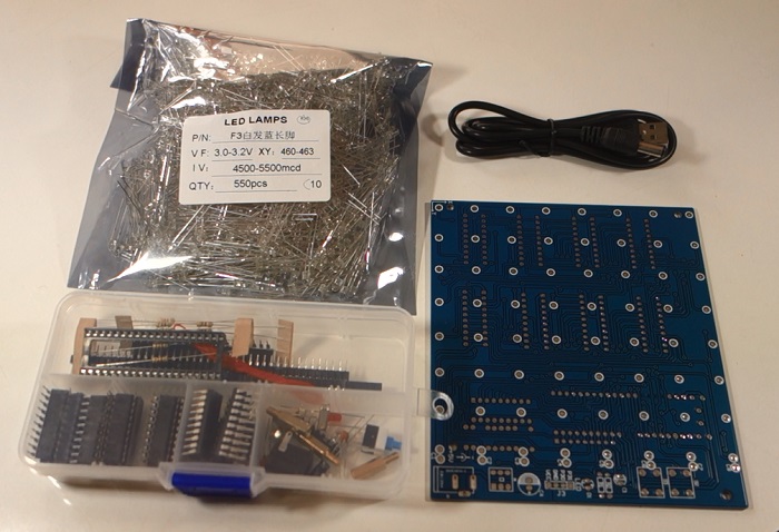
There is a description of all the components that come with the kit in the product page.
1. Separate and Solder the Header Pins
The kit comes with two sets of 40 header pins. You need 72 for your kit.
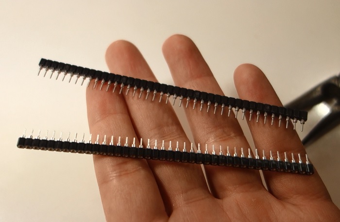
With a wire cutter, break the plastic of the header pins, and separate each header.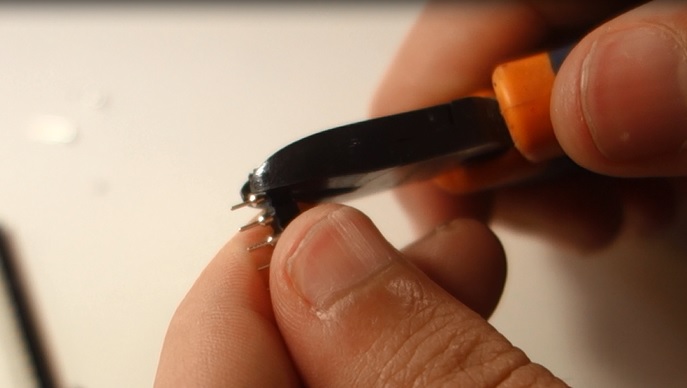
Be careful not to bend the headers! The following figure shows what you should have after breaking the plastic part.
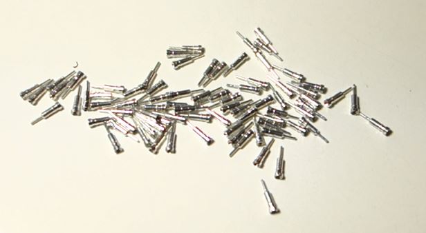
Insert the header pins pointy end into a white circular hole at the top of the PCB (the part marked with a x and y axis at the corner) as shown in the figure below.
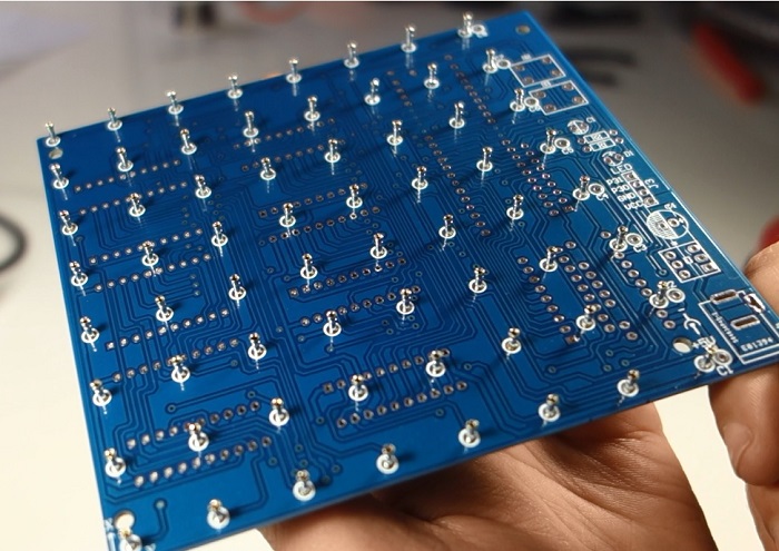
Then, solder all the 72 header pins.
Note: in the figure above we hadn’t yet soldered the pins at the rightmost column, but you should solder all those pins.
Make sure all the pins are as vertical as possible, because that will make your LED cube look aligned in the end..
2. Solder the PCB Bottom Components
Solder the PCB bottom components:
- 10x DIP sockets,
- 8x 510 Ohm resistors
- 2x ceramic capacitors
- 1x cristal
- 1x resistor array
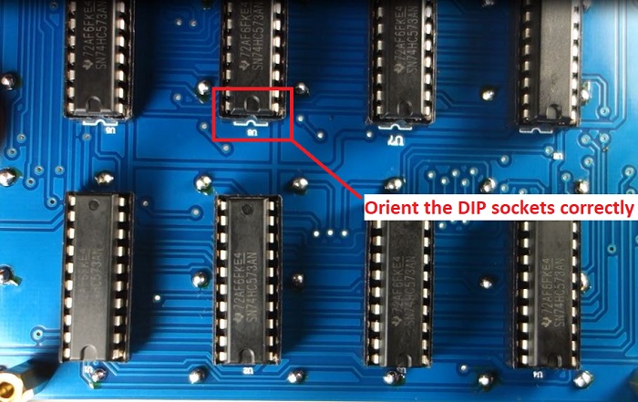
Start soldering the smallest components, and then solder the DIP sockets. Don’t connect the chips yet. You should seat the chips when you finish soldering all the PCB components.
Make sure you orient the DIP sockets correctly by following the half-circle orientation.
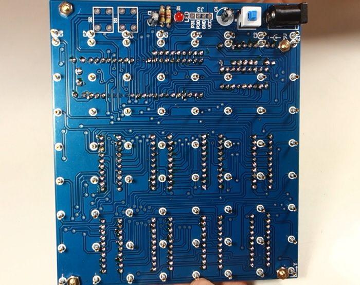
The following figure shows how your PCB bottom should look after soldering the components. You can use the figure below as a reference to know where to solder each component.
Note: again, don’t connect any of the chips yet.
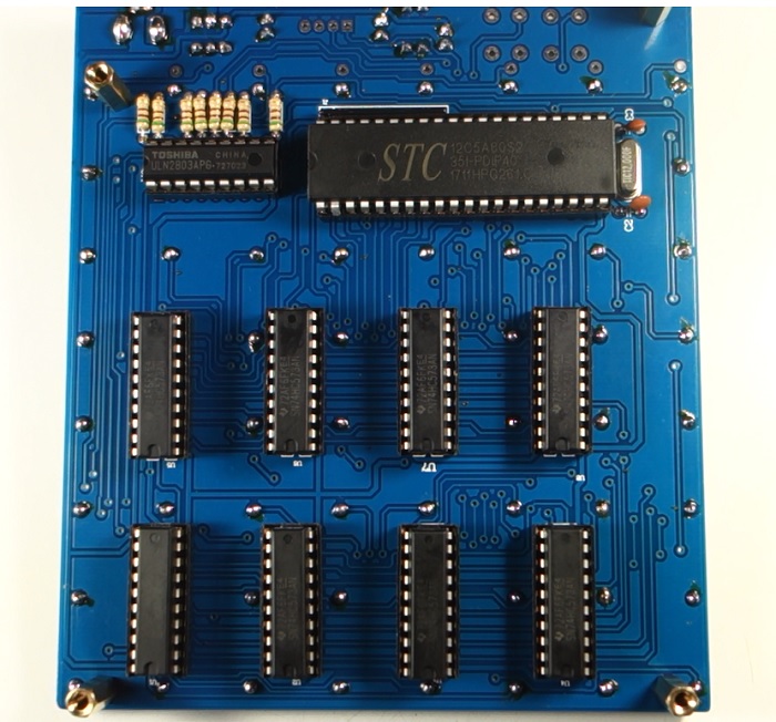
Make sure you solder the resistor array in the right orientation. When the PCB is on the following orientation, the letters of the resistor array should be facing at the back.
3. Solder the PCB Top Components
The next step is soldering the components at the top. Here are the components you need to solder at the top:
- 2x electrolytic capacitors – electrolytic capacitors have polarity, make sure you place them in the right orientation
- 1x LED – LEDs have polarity too
- 2x 4.7k Ohm
- 1x power jack
- 1x switch
Start by soldering the smaller components, and then the bigger ones. Pay attention to the components that have polarity. You can use the following figure as a reference on where to place each component.
After soldering all the components, you can place the chips in the sockets. Be careful not to break any lead.
4. Test the PCB
After soldering all the components in the PCB, you should check that everything went well
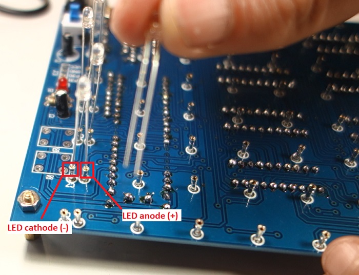
Place 8 LEDs in the PCB as shown in the figure below, with the anode and cathode place as shown. The cathode should be placed in the headers maker with “C1”, “C2”, “C3”, etc.
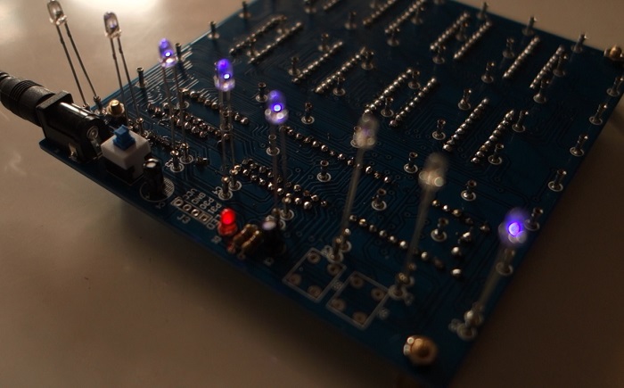
Apply 5 V to your circuit, and press the switch. The LEDs should light up and display an animation.
Important note: your LED cube kit will only display an animation if it comes programmed by default. If it doesn’t, you’ll probably won’t see any effects.
Important note: don’t start soldering any LED grids until you make sure your circuit is working properly.
If your LEDs don’t light up, double-check all your connections. Make sure the chips are well placed in the sockets without any broken pins. Also, make sure you’ve oriented the LEDs correctly.
Note: if you’re using a sightly different kit, swap the LED anode with the cathode and see if it works. If it works, take note of your LEDs orientation, because you’ll need to know that for the next steps.
5. Build a Cardboard Grid
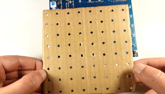
The header pins at the PCB are spaced 15 mm from each other. So, you should make a grid with 15 mm spacing. As the LEDs have 3 mm diameter, you should make 3 mm diameter holes at the edges, as shown in the figure below.
You can click here to download the grid at the right scale. You just need to print it as it is.
Note: if your kit has a different spacing, your grid will have different dimensions.
Glue the sheet with the grid to a piece of cardboard, and use it as a reference to mark the holes in the cardboard. You can use a sharp object, a screwdriver, or anything you have at hand to make the holes.
Then, check that your cardboard aligns with the header pins of the PCB.
6. Bend the LEDs
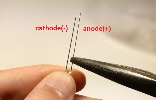
Orient the LED as in the figure below. With the longest lead, the anode (+), to the right, and the shortest lead, the cathode (-) to the left.
Using a needle nose pliers, bend the longest lead backwards with a 90º angle. As shown in the figure below. You should do this to all needed LEDs.
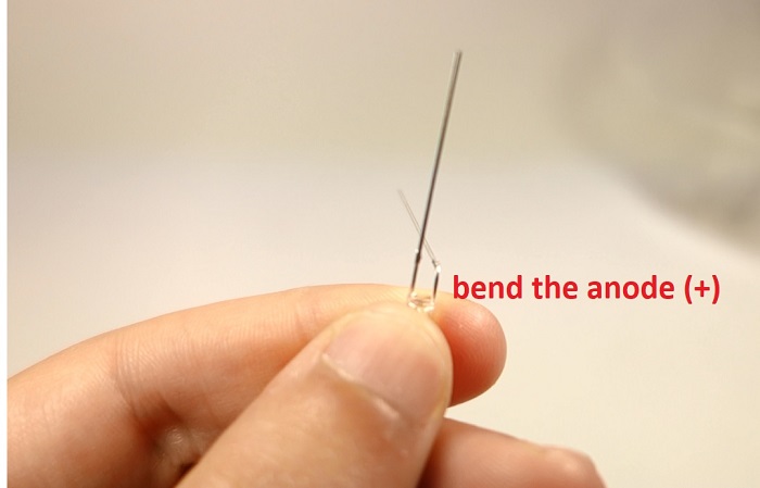
Warning: pay attention while you bend the LEDs, don’t bend the wrong lead, or you’ll end up switching the anode with the cathode when you mount the LED grids .
Note: If in step 4, your LEDs are positioned with the anode and the cathode in a different orientation (in case you have other kit), you should place the LED so that the cathode is at the right, and then bend the cathode.
7. Solder the LEDs’ Anodes
Insert the LEDs into the cardboard as shown in the figure below. The LED cathode (the shortest lead) is pointing up, and the LED anode (the longest lead, that is bent) is pointing to the right.
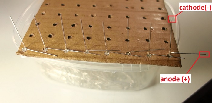
Solder the anodes together. Then, you should have a row of soldered LEDs.
Warning: when soldering the LEDs, it’s very important to do it quickly. Each solder joint shouldn’t take more than 1 or 2 seconds, otherwise you might fry the LED.
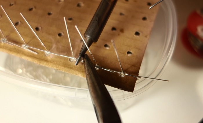
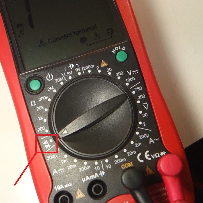
Test the LED row with your multimeter. Put your multimeter in continuity/diode testing mode.
Place the red probe at the first LED anode, and touch the cathode with the black probe. The LED touched with the black probe should light up.
If one of the LEDs doesn’t light up, there are some possible scenarios:
- There’s a faulty soldering joint;
- you’ve accidentally switched the LED’s leads;
- The LED doesn’t work – should be replaced with a new one.
Repeat the process until you fill the cardboard with eight rows. Always test each individual row as you solder. It will be much difficult replacing faulty LEDs after the cube is done.
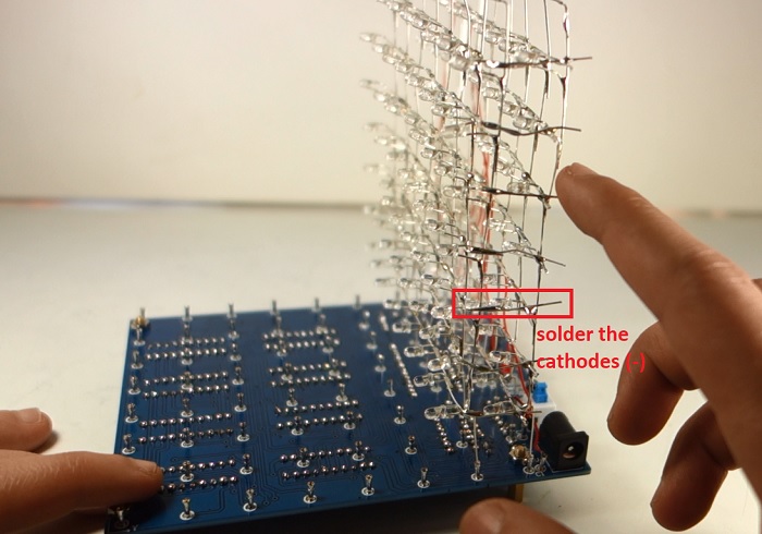
8. Solder the LEDs’ Cathodes
Once you have the cardboard filled with 8 rows of LEDs, you need to solder the LEDs’ cathodes together. For this step, we recommend getting something with approximately 5 mm height to help you bend the LEDs. We’ve used a screwdriver.
Place the screwdriver between the LED rows as shown in the figure below.
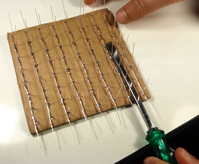
Then, bend the LED cathodes to the right – take a look at the following figure.
Then, solder the cathodes together.
Warning: pay attention because the anode and the cathode rows shouldn’t touch each other.
Then, with your multimeter in continuity/diode mode, test if all the LEDs are working properly.
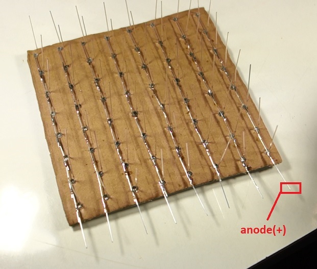
Repeat this process until you have all the cathodes soldered to each other. In the end, you should have an LED grid as shown in the figure below.
Detach the LED grid from the cardboard.
9. Repeat 8 Times
Repeat steps 7 and 8 eight times until you have 8 LED grids . That’s a lot of soldering – to give you an idea, we took approximately 45 minutes to solder each grid.
10. Insert the LED Grids in the PCB
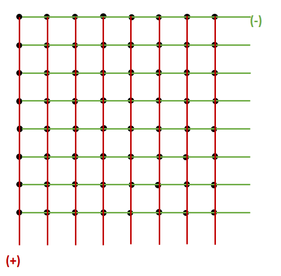
Once you have all your LED grids ready, the next step is inserting the grids in the PCB header pins. You should connect the anodes (+) of the LEDs to the header pins.
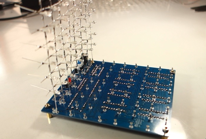
You need to be very patient in this step. Inserting the leads in the header pins is a bit tricky, and you have to be careful not to break any connection.
Warning: don’t connect LEDs to the header pins marked with a “C” – those pins are needed to connect the cathodes.
Don’t solder the other grids right now.
11. Connect the Cathodes to the PCB
You need to connect the cathode of each row to the “C1”, “C2”, “C3”, etc, header pins. For that, you need to cut the insulating wire that comes with the kit in several pieces with the right length.
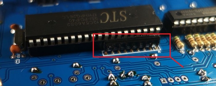
Then, connect the cathode of the first row to the “C1” header pin. Connect the cathode of the second row to the “C2” header pin, and so on, until you have all the rows connected to the header pins. Take a look at the following figure to see what you should get.
Important note: we’ve soldered the grids in the wrong orientation. In steps 11-14 , your LED cathodes should be facing the opposite side shown in the images. All the images in the previous steps are correct.
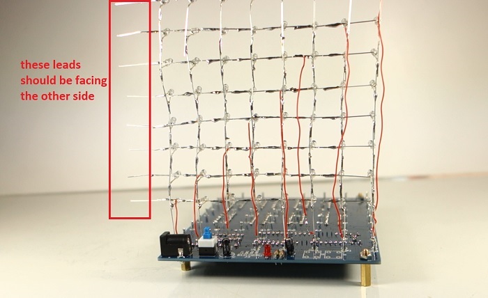
For example, in this image the LEDs’ leads are on the left side, but yours should be facing the right side, when the cube is in this orientation.
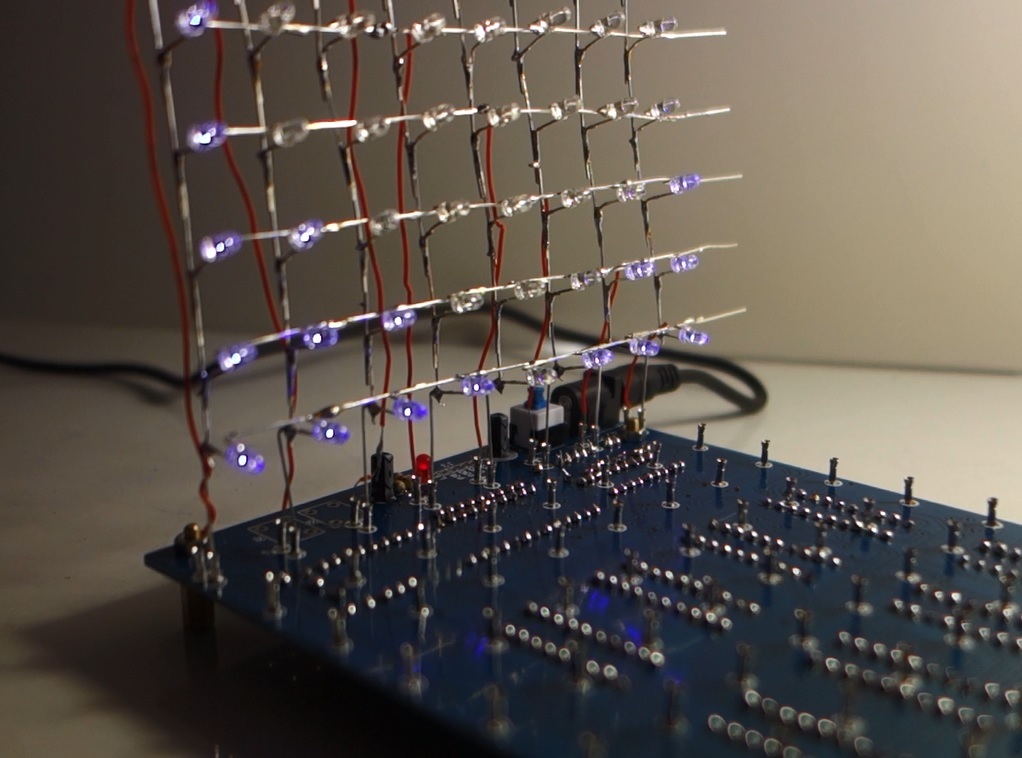
12. Test the LED Grid
Once you’ve soldered all the cathodes, test your LED grid. For that, apply power to your cube and press the switch.
Your LED grid should make an animation. Verify that all LEDs are working properly. If not, carefully check all the connections.
Note: your LED cube kit will only display an animation if it comes programmed by default. If it doesn’t, you’ll probably won’t see any effects.
Important note: we’ve soldered the grids in the wrong orientation. In steps 11-14 , your LED cathodes should be facing the opposite side shown in the images. All the images in the previous steps are correct.
13. Connect the LED Grids Together
After the first grid is properly placed in the PCB, insert the second LED grid into the PCB. Then, solder the free cathodes leads with the cathodes leads of the previous grid, as shown in the following figure. Your LEDs cathodes should be on the left side of the cube.
Important note: we’ve soldered the grids in the wrong orientation. In steps 11-14 , your LED cathodes should be facing the opposite side shown in the images. All the images in the previous steps are correct.
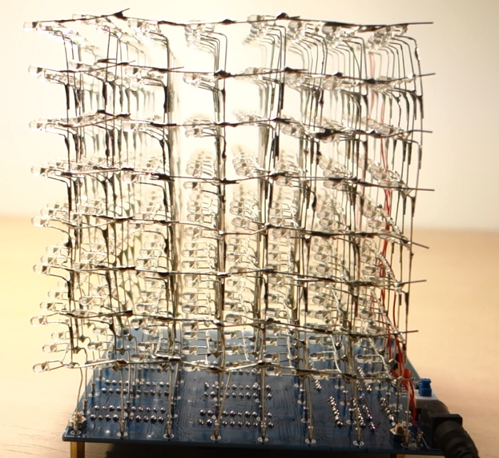
Repeat this process until you have all your LED grids in place. The next figure shows how all the LED grids look like when soldered.
Important note: we’ve soldered the grids in the wrong orientation. In steps 11-14 , your LED cathodes should be facing the opposite side shown in the images. All the images in the previous steps are correct.
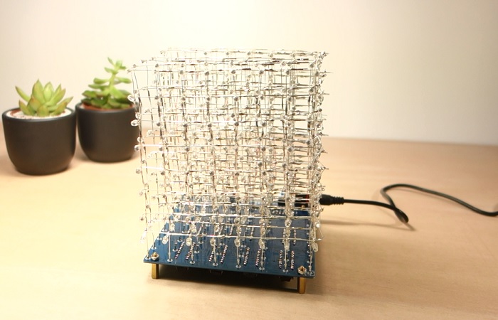
14. Finished!
Congratulations! Your 8x8x8 LED Cube is finished. Here’s how it looks like:
Demonstration
Apply power to your cube, press the power switch, turn off the lights, and enjoy the awesome animations. Here’s a gif image with some of the animations.
Watch the following video demo to see the 8x8x8 LED Cube in action!
[EXTRA] Programming the LED Cube
If your LED cube kit doesn’t make any effects, and you’ve assembled everything right, you probably get a kit that doesn’t come programmed.
If that is the case, there are some instructions on how to program the 8x8x8 LED cube kit in the following links:
Wrapping Up
In this post we’ve shown you how to assemble the Geekcreit 8x8x8 LED Cube DIY kit from Banggood. The kit came with all the needed parts, plus a few extra components if you need replacements. The kit doesn’t come with instructions on how to assemble. So, that’s why we’ve documented all our building process.
We believe that our instructions can help a lot of people building their LED cubes in an easy way. Soldering this cube was a lot of fun, and the end result is just awesome.
If you we’re thinking about grabbing one 8x8x8 LED cube DIY kit, go for it – you can follow our instructions, so the build will be a piece of cake. Click the product card below to buy your cube at Banggood:
Please note that this kit takes some hours to build, patience, and soldering skills.
We have articles about other DIY kits you may like:
- DIY Transistor Tester Kit Review
- JYETech DSO150 Digital Oscilloscope Review
- XR2206 Function Generator DIY Kit Review
We hope you’ve found these instructions useful.
Looking for more reviews? Make sure you subscribe here to catch upcoming reviews and deals!
Thanks for reading.
[Recommended Course] Learn ESP32 with Arduino IDE
Register in our brand new ESP32 course with Arduino IDE. This is our complete guide to program the ESP32 with Arduino IDE, including projects, tips, and tricks! The registrations are open, so sign up now.
Other RNT Courses
 [eBook] Home Automation using ESP8266 »
Build IoT projects and home automation gadgets with the ESP8266 Wi-Fi module.
 [Course] Build a Home Automation System »
Build a home automation system using open-source hardware and software.
 [Course] Arduino Step-by-Step Projects »
Build 25 cool Arduino projects with our course even with no prior experience!
Leave a Reply